


The Breker Trekker Tom Anderson, VP of Marketing
Tom Anderson is vice president of Marketing for Breker Verification Systems. He previously served as Product Management Group Director for Advanced Verification Solutions at Cadence, Technical Marketing Director in the Verification Group at Synopsys and Vice President of Applications Engineering at … More » Composition, Chaining, and Vertical Reuse with TrekUVMAugust 20th, 2014 by Tom Anderson, VP of Marketing
Several posts back, we introduced the idea of “composing” higher-level verification elements from low-level elements with little or no effort. We discussed how this was not possible with traditional testbench elements such as virtual sequencers and scoreboards. We showed that Breker’s graph-based scenario models can be simply combined from the block level to the cluster level, and from the cluster level to the full-chip level. Last week, we took the unusual step of announcing a new EDA product via social media rather than a traditional press release. The news about TrekUVM clearly spread; we had a nice spike in blog readership and an even bigger spike in traffic to our Web site. Since our readers have interest in this new product, we’d like to continue talking about it and, specifically, show how it fosters model composition and vertical reuse.
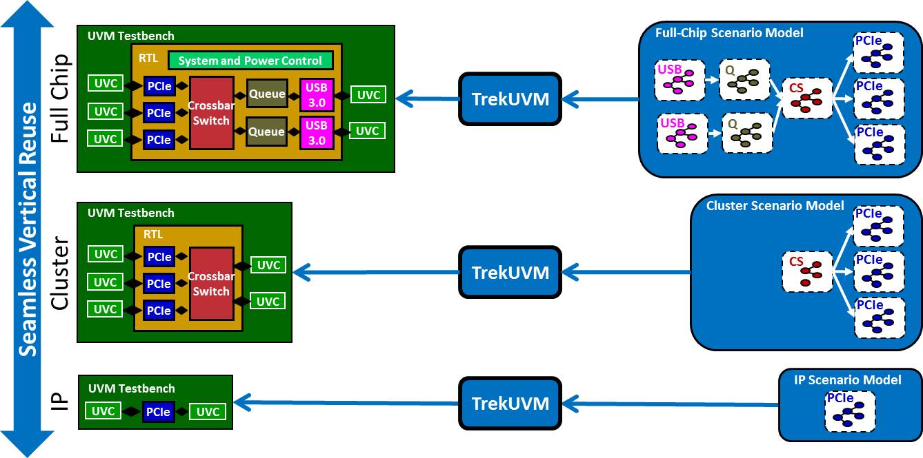
First we’d like to revisit a figure from our earlier post. Two low-level blocks, X and Y, were each verified using graph-based scenario models. These two blocks are now connected at the next highest level of the design hierarchy. The verification team can create a scenario model for the combined blocks by composing the two graphs. Some of our customers prefer the term “chaining” since they are truly chaining together two existing scenario models to make a higher-level model. Again, this is an intrinsic feature of graphs that does not apply for other types of verification testbench elements. If we return to the non-SoC networking chip example we used in our last post, we can see that TrekUVM supports composition/chaining exactly as you would expect from a solution using graph-based scenario models. Since TrekUVM supports any transactional UVM (or other constrained-random) testbench, it can be used to verify individual IP blocks. Although pure UVM is often viewed as sufficient for block-level verification, using scenario models makes it easier to describe complex protocols and converges more quickly on block-level coverage goals.
Perhaps the best reason to use TrekUVM at the block level is vertical reuse. The block-level graphs can be composed, or chained together, to produce scenario models for higher levels of the chip hierarchy. Many of our customers use the term “cluster” to refer to a collection of IP blocks that perform a significant subset of the overall chip functionality. The cluster-level scenario model and TrekUVM cab be used to verify each cluster in the design. Finally, the cluster models can be composed/chained to produce a full-chip-level graph-based scenario model. At this level, a pure UVM testbench is inefficient and so TrekUVM is a necessity to thoroughly exercise all corner cases and converge on coverage goals more quickly. TrekUVM’s ability to report unreachable coverage targets is also highly valuable, because otherwise the verification team could waste thousands of simulations trying to achieve a coverage goal that is mathematically impossible. Some users of Breker’s graph-based verification products do start at the IP level and reuse scenarios as they assemble the chip and move up the design hierarchy. Others are satisfied with their UVM-based testbenches at the lower levels but bring in Breker for verification of the complete chip and perhaps a couple of the largest clusters. In this case, the verification team may worry that they have to create scenario models for every part of the chip even though they are done with block-level verification. They need not be concerned. The goal of cluster-level or chip-level verification is not to repeat the full range of verification performed stand-alone for each design block. Rather, the focus is on verifying that the assembled pieces of the chip interact properly. This requires a much less detailed model of each IP block. The chip-level verification team does not have to become an expert on every block in the system in order to do their job. To summarize, TrekUVM fosters vertical reuse for chips with transactional UVM testbenches in much the same way that TrekSoC supports reuse for system-on-chip (SoC) designs with embedded processors. There is no known technology that supports reuse and test case portability better than our graph-based scenario models. Tom A. The truth is out there … sometimes it’s in a blog.
Tags: Breker, coverage, EDA, functional verification, graph, portable stimulus, reuse, scenario model, scoreboard, sequencer, SoC verification, transactional, TrekSoC, TrekSoC-Si, TrekUVM, UVC, uvm 3 Responses to “Composition, Chaining, and Vertical Reuse with TrekUVM”Warning: Undefined variable $user_ID in /www/www10/htdocs/blogs/wp-content/themes/ibs_default/comments.php on line 83 You must be logged in to post a comment. |
|
|
|||||
|
|
|||||
|
|||||


 Animation, 3D Art and 3D Models")
>>The goal of cluster-level or chip-level verification is not to repeat the full range of verification performed stand-
>> alone for each design block.
Considering above fact, how does initial stated vertical reuse makes sense? Block level graphs wouldn’t it have different focus than cluster or full chip level ?
Excellent question, Anand. Indeed the graph used at higher levels does not have to be as detailed as for block-level verification. There are two paths here. For a project using TrekUVM primarily at the full-chip or cluster level (top-down), the graphs for individual blocks often reflect only a subset of the full block functionality. As you correctly said, the goal at higher levels is not to exercise every aspect of every block. This also means that the chip-level verification team doesn’t need to know every detail of every block, just enough functionality to do a good job of testing multi-block scenarios.
For a project using Trek UVM for block-level verification and then moving up (bottom-up), the scenario models for the blocks will likely reflect more functionality than is needed at higher levels. Graph constraints can be used to “trim off” parts of the scenario model that are not relevant for cluster-level or full-chip verification. For example, a block might have 16 different modes that are randomized in block-level verification, but there is no value in exercising all those modes at the chip level so a constraint could select just one.
Again, you asked a great question. Please let me know if my answer is clear enough. Thanks!
Tom A.
Got it, Tom. What I understood is, block level graphs can be trimmed through the graph constraints to make them vertical reuse friendly for the cluster-level or full chip level. Thanks.
Just curious: Are graphs Object oriented? What I mean, Is trimming through some equivalent of inheritance type concept or does it need modification to block level graph ?