The Breker Trekker Tom Anderson, VP of Marketing
Tom Anderson is vice president of Marketing for Breker Verification Systems. He previously served as Product Management Group Director for Advanced Verification Solutions at Cadence, Technical Marketing Director in the Verification Group at Synopsys and Vice President of Applications Engineering at … More » Two Peas in a Pod: Scenario Models and System CoverageSeptember 10th, 2013 by Tom Anderson, VP of Marketing
In our last technical blog post, we surveyed some of the existing forms of coverage, including their virtues and limitations, and their applicability to SoC designs. We also introduced a new type of metric, system coverage, based on application scenarios that reflect how an end user would actually run applications on the SoC. We closed by claiming that “Breker’s graph-based scenario models are ideal for establishing, measuring, and refining system coverage.” This is the next in a series of posts to explain why and how. Another earlier post described the Breker approach of “beginning with the end in mind” using graph-based scenario models. In the graphs used by TrekSoC, outcomes appear on the left and inputs appear on the right, reflecting the way that the test case generator works from the desired result toward the setup conditions needed for a particular application scenario.
Each walk through the graph generates a different application scenario, randomly choosing different paths at decision points and randomizing other aspects of the test (data, addresses, etc.) as specified in the scenario model. These application scenarios may be scheduled serially on a single-threaded, single-processor SoC or intermingled on a multi-threaded or multi-processor architecture. The resulting test case is compiled and run on the embedded processors in simulation.
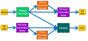
However, at the top level of this SoC, there are only four different types of application scenarios, or paths through the graph:
This example shows why scenario models and system coverage work so well together. The four realistic application scenarios appropriate for this digital camera fall out directly from the different paths through the model. One way to think about this approach is that the scenario model serves as the system specification and that system coverage can automatically be extracted from this model. This example does not imply that only four system test cases are needed to verify a digital camera at the system level. TrekSoC provides many options for test case generation to ensure that the design is stressed well. Although it is neither desirable nor practical to repeat standalone IP verification at the system level, it may be important to ensure coverage on some of the decision points within the IP blocks. There are many more details on how users interact with scenario models, control test case generation, and analyze coverage results. Future blog posts will continue to “peel the onion” on the very important topic of system coverage. As always, any questions or comments are most welcome. Tom A. The truth is out there … sometimes it’s in a blog. Tags: Breker, functional verification, graph, scenario model, SoC verification, system coverage, test generation, TrekSoC Warning: Undefined variable $user_ID in /www/www10/htdocs/blogs/wp-content/themes/ibs_default/comments.php on line 83 You must be logged in to post a comment. |
|
|
|||||
|
|
|||||
|
|||||


