| |
Chapter 7
Coverage Directed Verification Methodology
Coverage Analysis in the Design Flow
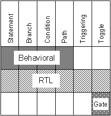
As discussed in an earlier chapter, coverage analysis can be applied at any (or all) of three stages in the design flow, namely, at the behavioral level of the design, at the RTL level, and at the gate level. Most time is usually spent at the RTL stage. Transforming designs to gate level is almost a fully automatic process and relatively little time, if any at all, is spent doing behavioral design. There are two likely reasons for this lack of time spent at the behavioral level. First, a behavioral description is very far removed from the actual implementation of the design and, second, there is no automatic route to a physical device from behavioral level and, because designers are under pressure to get to the `real design' they relate to RTL and gates more readily than abstract behavioral descriptions.
Coverage Analysis at Behavioral Level
Simulation is still carried out at the behavioral level to ensure that the ideas captured comply with the design specification. It is therefore appropriate to use coverage analysis at the behavioral level to ensure that the whole description is verified. The behavioral description is much smaller than the RTL description because it is a higher-level form of the design and as such it is appropriate to run coverage analysis only on the full behavioral description as it nears completion.
Behavioral descriptions contain abstract types such as real numbers and enumerated types and records of types (in VHDL) and the code tends to be written in large procedural blocks (processes, functions, procedures, always blocks, and tasks). It is for this reason that not all coverage analysis measurements are appropriate at behavioral level.
Toggle coverage is concerned with simple binary signals which are less common in behavioral descriptions therefore in general toggle coverage is not appropriate.
The measurements that test procedural code such as statement, branch, condition and expression, path and triggering coverage should be used on the behavioral design.
Coverage Analysis at RTL
We have already seen that the RTL design process is very complex and results in large descriptions and that the process has to be subdivided to make it more manageable and to allow a larger design team to work on the project. To recap Figure 7-1 shows the three parts of the RTL design process - module design, subsystem integration and system integration.
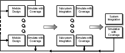
At the module design stage the descriptions are relatively simple and the simulations tend to be short. It is appropriate to ensure that the module is thoroughly verified before it is integrated into the subsystem, as problems are harder to track down as the design complexity increases. Coverage analysis should be employed as part of this thorough module verification. In order to ensure that a module has been completely verified all coverage measurements should be used at this stage.
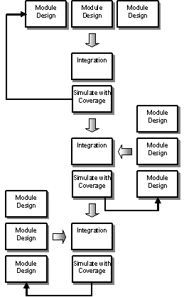
At the subsystem integration stage the simulations are becoming longer, up to a few hours each, and the subsystems are likely to consist of large amounts of RTL code. The amount of data that can be produced by a coverage analysis tool can be extremely large and the overhead on the simulations - although only a small percentage - can be significant in actual time. It is still essential to ensure that module interfaces and `glue logic' is thoroughly verified and that each module's behavior is fully tested within the subsystem. It is for this reason that it is sensible to use a subset of the coverage measurements. As an absolute minimum it is essential to check that every statement has been executed and every branch decision has been taken. In addition toggle coverage ensures that a minimum range of data values has been passed through the design. Finally it is important to verify every expression has been thoroughly tested. Subsystem integration is not a trivial process therefore coverage analysis should be used throughout the subsystem design phase in order to ensure that any integration problems are trapped early and not left to cause problems at a later stage. This is shown graphically in Figure 7-2.
System integration is very similar to subsystem integration except that the blocks being integrated are significantly larger - as are the quantity and duration of the simulations at this stage. It is therefore appropriate to only use a subset of coverage measurements at the system integration level. We would recommend the same measurements used at subsystem level, that is - statement, branch, condition and toggle coverage. Time pressure, however may dictate that less coverage information is collected to make simulations shorter and to reduce the time required to analyze the coverage results. If this is the case the absolute minimum measurements we would recommend are statement and branch coverage.
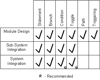
Figure 7-3 summarises the coverage measurements that should be used at each stage of the RTL design process.
Coverage Analysis and Transient Behavior
HDL simulations can contain transient behavior because of the order in which assignments are executed during the simulation. The temporary signal value changes caused by this transient behavior are often referred to as glitches. These glitches result in lines of code being executed but the results of the execution are overwritten in the same time step.
Figures 7-4 and 7-5 show examples of Verilog code and VHDL code respectively which will create glitches on signal `d' when the signals `a' and `b' both change simultaneously.
The examples in figures 7-4 and 7-5 are fairly contrived but it does prove it is very easy to write HDL code that contains glitches.
Glitches in the simulation affect the coverage analysis results, the simulator executes statements because of the glitches and coverage analysis records this execution. The recorded behavior is transient and therefore is not checked by the test bench. This does not make the coverage wrong but it does mean that the transient behavior is not properly tested. It is therefore more useful if the coverage tool can exclude transient behavior from its results. Not all coverage tools have this capability; Verification Navigator from TransEDA is one that does.
Coverage Analysis at Gate Level
At gate level there are no statements and expressions to verify with coverage analysis. The only measurement which is appropriate at gate level, and is available in most coverage tools, is toggle coverage.
One of the other tasks performed during gate level design is fault simulation. The purpose of fault simulation is to create a set of tests to verify the physical device once it has been manufactured. Fault simulation takes a great deal longer than normal simulation; therefore anything that can be done to minimize the time spent doing this will help reduce the overall time spent in gate level design.
Fault detection relies on two characteristics. The first is controllability - ensuring both logical 1 and 0 can be applied to every node in the circuit by applying values to the input pins. The second is observability - ensuring that the effect of a fault on every node can be propagated through the circuit and observed on the output pins. Without a high degree of controllability the fault simulation results will be very poor. By making sure the controllability of the circuit is high before starting fault simulation means that expensive fault simulation time is not wasted.
Toggle coverage is directly proportional to circuit controllability, therefore running a normal simulation with toggle coverage allows you to ensure you have adequate controllability before starting fault simulation.
Coverage Analysis and State Machines
State machines can be described in RTL code explicitly or implicitly. Explicit descriptions have the state transitions explicitly written as assignments in the HDL code. In implicit state machines the next state logic is written as a series of expressions. It is very difficult to determine state machine behavior by looking at the HDL code of an implicit description. Figures 7-6 and 7-7 show an example of the next state logic for a two-bit counter described explicitly and Figures 7-8 and 7-9 show the implicit form of the same logic.
next_state[1] = (!state[1] && state[0]) || (state[1] && !state[0]);
next_state(1) = (NOT state(1) AND state(0)) OR (state(1)
In terms of verifying state machine coverage, transition coverage on explicit styles will be measured by statement coverage. With implicit styles it is difficult to relate missing coverage to the transitions of the state machines, however 100% condition coverage will ensure that all the behavior is tested.
With state machines it is critical to use a deglitching facility if it exists otherwise transitions that are not actually latched in the state register could be counted because of the transient behavior.
Coverage analysis tools record transition behavior but they do not record the order in which the transitions are executed or sequence of operations of the state machine. To verify sequences have been covered a specific state machine analysis tool such as Verification Navigator's FSM coverage tool from TransEDA is required.
Practical Guide Lines for Coverage Analysis
All coverage analysis tools can produce a vast amount of information and there is always an overhead associated with collecting this information, therefore you need some practical guidelines for using these tools. We have already discussed the measurements that should be used at different stages in the design process and Figure 7-10 summarizes this information.
By restricting the measurements that you use as the design becomes more complex will help to make the data produced more manageable. The way in which the data is presented is also important. Verification Navigator from TransEDA is particularly good at presenting the information in an easy to understand graphical interface.
We have also discussed glitches in the design behavior and how these can affect the coverage results. Most coverage tools have a deglitching capability. However the overhead of using this is greater than normal and it is therefore recommended that deglitching be used only at the end of each stage in the design process.
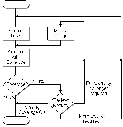
In some cases when the coverage tool shows that there is a construct which has not been completely covered due to some constraint in the design it may be impossible to achieve 100% coverage analysis. It is for this reason that the coverage analysis tool should be used as a `verification advisor'. The tool should be used to measure how much of the design has been verified. Then a design review should be held to determine 1) if it is possible to achieve a higher coverage with further tests, 2) if the uncovered part of the design has functionality which is no longer required, and therefore can be removed from the design and 3) if the omitted coverage is acceptable within the scope of the design. This process is shown in Figure 7-11.
Coverage Analysis as a Verification Advisor
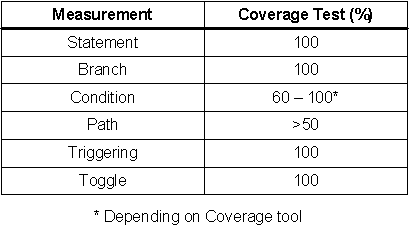
Software tools are produced to help people with their design and verification tasks. That is why we feel that you should not be a slave to the coverage figures and should not necessarily strive for 100% coverage if it does not make sense within the scope of your design. It is however up to you as design and verification engineers to decide what parts of the missing coverage are important to you. Figure 7-12 shows the sort of coverage analysis targets that should be aimed for.
Coverage Measurements and Targets
Every statement and branch of your code should be executed. The only exceptions to this rule are error checking code - which should not normally be executed - and extra case or if branches which are added for synthesis tools. Some coverage analysis tools allow meta comments to exclude such code from consideration to make the review process simpler.
It should be possible to toggle every signal in your design, the only exceptions should be constant signals such as power and ground.
In terms of testing expressions, the value that should be aimed for is dependent on which coverage analysis tool you are using. Not all 2^N combinations (where N is the number of inputs) are generally required to fully verify an expression. In most cases it is 2N + 1. This makes a significant difference to the verification time. For example a 4 input expression can have 16 possible input combinations but usually only 5 of these are required to fully verify the expression. Some coverage analysis tools take account of this fact. For example Verification Navigator has a measurement called Focused Expression Coverage. When using such tools, a high percentage condition coverage should be aimed for. If your coverage analysis tool mandates that you must test your expressions with all possible input combinations then it is unlikely that you will be able to achieve a high percentage and a figure of 60% may be the best that can be achieved.
Not all coverage tools contain path coverage and the value you should aim for is very much dependent on your design style. If your paths are independent - that is signals in the first branching construct of a path are not reassigned or used in the second - then path coverage is not important. Figure 7-13 shows such an example.
Figure 7-14 shows an example of paths that are not independent and therefore path coverage is important. In this example a divide-by-zero error could be missed if the paths are not fully verified. We have already suggested that path coverage should be used at module level verification therefore it should be relatively simple to review the path coverage results and determine if the missing coverage is significant.
A high percentage process triggering coverage should also be obtained otherwise the process sensitivity list may in fact be wrong and could lead to different behavior after synthesis.
Saving Simulation Time
The final key to using your coverage tool effectively is to minimize the simulation overhead by only turning coverage on for the parts of the design that you are interested in. This may be because you are running full chip simulation but are only interested in verifying a small part of the total design, or you have already achieved a desirable level of coverage on the rest of the design and you are adding tests to increase the coverage on a particular part. In either case there is no need to record coverage information you are not going to use.
Number of Coverage Analysis Licenses Required
As discussed earlier, coverage analysis should be performed at the module level. This means that every engineer performing verification at this stage must have access to the coverage analysis tool. As a general approximation one coverage license between three engineers should be sufficient because the simulation runs are fairly short at this stage. The ideal would be a one-to-one correspondence between verification engineers and coverage licenses.
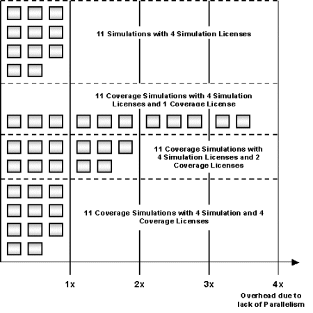
The major problem is running coverage on subsystem and system regression tests, in general at this stage in the design process the verification team runs many simulations in parallel. If you have a limited number of coverage licenses, the number of coverage simulations which can be run in parallel is limited, and therefore the time to run the regression tests is extended significantly. An example of this is shown in Figure 7-15. The ideal solution is to have the same number of coverage simulation licenses as simulator licenses. If this is not possible because of project budgets, a workable minimum ratio is between 3:1 to 5:1 simulator to coverage licenses.
|
|
|