


The Dominion of Design Sanjay Gangal
Sanjay Gangal is a veteran of Electronics Design industry with over 25 years experience. He has previously worked at Mentor Graphics, Meta Software and Sun Microsystems. He has been contributing to EDACafe since 1999. Using Simulation to Optimize Safety, Performance, and Cost Savings When Integrating an Antenna Onto a PlatformFebruary 7th, 2013 by Sanjay Gangal
Article source: Remcom Successful integration of an antenna onto a vehicle platform poses many challenges. Vehicle features impact antenna performance by blocking, reflecting or reradiating energy, and co-site interference can impair the effectiveness of multi-antenna configurations. Platform motion and environmental factors such as terrain and buildings may reduce system effectiveness in actual op The key benefit of simulation-based assessment is that it is relatively fast and cost-effective compared to physical system modification and measurement. The lead times and costs associated with scheduling measurements in an anechoic chamber or at an outdoor test facility sometimes strain schedules and budgets. Modeling and simulation can assess options and tradeoffs in order to select a small number of planned approaches well before any physical testing occurs; as a result, experimental design focuses on verifying planned approaches and fine-tuning alternatives demonstrated to be effective in simulations. This approach reduces the risk of encountering problems that require retesting, costly redesign or introduce dangerous in-theater behavior. In addition, a number of challenges arise when attempting to perform exhaustive laboratory or field testing on an integrated system. Some potential issues include:
A comprehensive modeling and simulation toolset allows an organization to overcome these challenges by being able to simulate any number of conditions, identify and resolve key issues, and reserve the use of physical measurements to confirm successful pre-test, simulation-based assessments. The remainder of this article provides several examples demonstrating typical simulation-based assessments to identify and resolve issues related to antenna performance and integration onto vehicles.
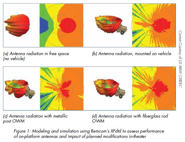
Assessing Performance of Antennas When Integrated on Vehicle Platforms High-fidelity electromagnetic solvers predict the performance of an antenna, including effects introduced by the features of a vehicle on which it is mounted. Figure 1 shows a series of results from simulations that were performed by the U.S. Army Communications-Electronics Research, Development, and Engineering Center (CERDEC) using Remcom’s XFdtd® software and an in-house ray-tracing tool. Figure 1(a) depicts the radiation pattern simulated in free space without any vehicle or other obstruction to perturb the pattern. Figure 1(b) shows the radiation pattern once the antenna has been mounted on a vehicle. Although the pattern has clearly changed, adding some significant back lobes and causing variation in the forward radiation pattern, the antenna exhibits similar forward radiation and gain to the original design. This type of simulation can be performed to evaluate any number of potential alternative configurations until a successful option is identified and selected for the final integration. Figures 1(c) and 1(d) illustrate how in-theater modifications complicate antenna performance. Figure 1(c) displays the pattern after modifying the vehicle with the addition of an Overhead Wire Mitigation kit (OWM) using a metallic post. Note: OWM prevents overhead obstructions such as clothes lines, power lines and foliage from damaging installed antennas. The impact is significant. A null forms in the main lobe reducing antenna gain forward of the vehicle. Replacing the metal post with a fiberglass rod, as shown in Figure 1(d), significantly improves performance with the return of strong gain in the forward direction. At higher frequencies, platforms may become electrically large, where electrical size describes the size of an object relative to the wavelength of a signal. Modeling an electrically large scenario using a full-wave solution such as the Finite Difference Time Domain (FDTD) method employed in XFdtd could require more memory or longer simulation times than desired, and a two-step hybrid approach may provide a more viable alternative. Figure 2 demonstrates the simulation of an X-Band antenna array mounted on a Global Hawk. The full-wave method from XFdtd determines the radiation pattern of the array on a metal ground plane. A solution based on the Uniform Theory of Diffraction (UTD) from Remcom’s XGtd® solver then calculates the radiation pattern resulting from mounting the array to the underside of the electrically large Global Hawk. This two-step process provides an accurate and efficient assessment of the overall performance of the antenna in its operational configuration. Assessing Co-Site Interference between Multiple Antennas Military vehicles commonly incorporate several antenna systems in close proximity. Interference between these systems can cause problems with simultaneous operation. As a first step in understanding the impact, the power coupling between each transmitting and receiving antenna must be assessed. This is typically done by simulating or measuring the power received at each installed antenna from every transmitting antenna. In the case of arrays, these transmitted and received powers must be summed appropriately in order to represent the real signals observed at the array’s input port. The ratio of received power to the transmitted power of the radiating system represents power coupling and describes how much of the transmitted power, in-band or out-of-band, propagates into the neighboring system. Figure 3 presents the results of an XFdtd simulation assessing power coupling between three conceptual antennas mounted on a HMMWV, as shown in Figure 3(a). A directional jammer antenna is modeled as an array mounted on the rear right of the vehicle. Power coupling is simulated from this antenna to three other antennas: a monopole communications antenna mounted on the rear left of the vehicle and a flat patch array on the front left roof that includes transmit and receive antenna arrays for satellite communication. Figure 3(b) shows the broadband power coupling from the jammer to each of the other antennas, with plot colors matching the arrows in the vehicle display.
This type of investigation helps analysts determine whether or not a transmitter affects the operation of neighboring systems and develop mitigation strategies if required. Examples of mitigation might include:
Simulation results assist with all of these approaches by enabling rapid consideration of alternative antenna configurations. Once pre-test modeling and simulation assessments are completed, measurements efficiently focus on confirming analyses and mitigation approaches. Assessing the Impact of the Environment on Antenna Performance The environment plays an important role in antenna performance. The presence of a dielectric ground plane in the near field of the antenna will alter radiation performance. As fields propagate to the far zone, interactions with the ground and structures cause interference due to multipath, which leads to constructive or destructive interference and shadowing. Nowhere is this interference more evident than in dense urban scenarios, where the specific layouts of buildings can become the single most dominant factor in the propagation of fields within the environment. Figure 4 demonstrates the multipath effects of buildings in an urban environment for two different scenarios, modeled within Remcom’s Wireless InSite® suite. Figure 4(a) shows received power from a transmitting antenna mounted on a HMMWV as it drives along a route through a city. Figure 4(b) presents the path loss for the array antenna on the Global Hawk shown earlier, as it flies high above the lower-left corner of the urban scene in the image. Both images assist in planning the operational use of the systems. At a fundamental level, consideration of the intended environment, such as assessing how ground beneath a vehicle impacts the effective range of a system, may also be used during integration to ensure that a system is able to perform its intended mission.
Assessing Potential Radiation Hazards to Personnel ANSI standards, DOD Instruction 6055.11, and numerous other government standards provide regulatory specifications for maximum permissible exposure (MPE) to protect personnel from radiofrequency (RF) radiation. When alternative systems and locations for mounting system antennas are being considered, one key factor must include consideration of the potential risk of radiation exposure to personnel. Figure 5 displays the magnitude of the electric fields that XFdtd predicts will enter the cabin of a HMMWV, mostly through its windows, from an antenna mounted on the roof. Information about electric and magnetic field strengths, frequency, duration, and duty factor of system transmissions combine in a relatively straightforward manner to determine whether the system is likely to exceed the MPE. At a more detailed level, it is also possible to use the FDTD method to estimate specific absorption rate (SAR) for a person modeled as sitting within the vehicle or standing nearby; however, field levels over time (as shown in the figure) are the usual metric for a radiation hazard assessment within the DOD.
Conclusion There are a number of critical issues to consider when integrating an antenna onto a vehicle platform, particularly when the intended use is for military operations. This article provides a small number of examples, including assessment of the impact of vehicle features on radiation, co-site interference from multi-antenna systems, and environmental obstructions to propagation, as well as analysis of potential radiation hazards. A variety of electromagnetic modeling solutions exist for analyzing various parts of the problem, and there are many cases where hybrid approaches using multiple solutions greatly assist in the overall understanding of the issues. By using these tools for simulation-based assessment prior to final antenna integration and laboratory or field testing, an organization can identify key issues and develop mitigation approaches cost-effectively. In this sense, modeling and simulation becomes one more tool to help ensure success when the system is finally deployed in the field. Tags: Antenna Category: Remcom |
|
|
|||||
|
|
|||||
|
|||||


 Animation, 3D Art and 3D Models")