Bit-Slice Design: Controllers and ALUs
by Donnamaie E. White
Copyright © 1996, 2001, 2002 Donnamaie E. White
- Pre-Introduction
- Selection of the Implementation
- Microprogramming
- Advantages of LSI
- The 2900 Family
- Language Interrelationships
- Controller Design
- Constructing the CCU
- Sequential Execution
- Multiple Sequences
- Start Addresses
- Mapping PROM
- Unconditional Branch
- Conditional Branch
- Timing Considerations
- Pipelining
- Improved Architecture
3. Adding Programming
Support to the Controller
- Expanded Testing
- Subroutines
- Nested Subroutines
- Stack Size
- Loops
- Am29811
- Am2909/11
- CASE Statement (Am29803A)
- Microprogram Memory
- Status Polling
- Interrupt Servicing
- Implementation - Interrupt Request Signals
- Vector Mapping PROM
- Next Address Control
- Am2910
- Am2910 Instructions
- Control Lines
- Interrupt Handling
- Am2914
- Interconnection of the Am2914
6. The ALU and Basic Arithmetic
- Further Enhancements
- Instruction Fields
- Instruction Set Extensions
- Sample Operations
- Arithmetic -- General
- Multiplication with the Am2901
- Am2903 Multiply
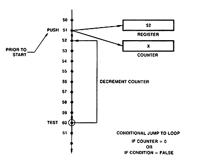
Adding Programming Support to the ControllerLast Edit November 1, 1996; May 1, 1999 ; July 9, 2001 Stack SizeHow large a stack is necessary? Since this stack is to handle microprogram subroutines and since the microprogram is composed of a number of microroutines which also modularize it, deep subroutine nesting is not desireable, nor is it necessary in the general case. For this CCU, a stack four deep is provided and assumed to be adequate. Depending on the ability of the stack to wrap, that is, if the pointer can move from position 4, binary address 11, to position 1, binary address 00 on the fifth successive PUSH without any intervening POP, various types of disasters can occur. The stack may or may not signal that it is full, depending on implementation details. The programmer is cautioned. LoopsAnother desirable programming feature is the ability to repeat one or more statements for some number of times until the number of specified repeats has been completed or until some specified condition occurs. This is the FOR-LOOP in programming languages. To handle such loops, the starting address must be storable and retrievable and a decrementing or incrementing counter must be provided. The CCU under construction will use a decrementing, settable counter. A basic flow for a loop is shown in Figure 3-6. Figure 3-6 Loop Flow. Conditional jumop-to-loop (CJP) activated if counter not equal to 0, or if CONDITION = FALSE.
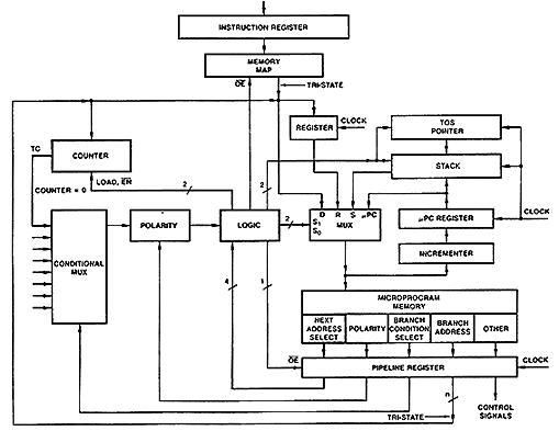
Tristate LinesThe hardware required will require a few changes in the basic CCU. First, there are no more available inputs into the next-address MUX. Rather than expand from a 1-of-4 to a 1-of-8 MUX, which would increase the microword size, we choose instead to reroute the pipeline branch address lines and have the branch address lines share one of the MUX inputs with the mappng PROM, since a start address and a branch address will never occur at the same time. To allow this sharing, the branch address portion of the pipeline register and the mapping PROM outputs must be tridtate lines and must have output enable control signals supplied by the next-address select logic. Start Address StorageThe register used to store the start address of the loop is added in aprallel with the address bus and may be loaded from the mapping PROM or from the pipeline branch address field. The register is connected to the next-address MUX. Register loading must be controlled by ewither the next-address logic control or by microinstruction control. CounterA counter is added such that it is loadable from the mapping PROM or a pipeline branch address field. The technique of allowing a microword format field. The technique of allowing a microword format field to be an address in one microinstruction and a count value in another microinstruction is called overlapping. The next-address control logic must control the load enable and the decrement control of the counter. The counter provides a status input to the condition MUX, which is used to determine when the contents of the decrementing counter reaches 0. The hardware for this version of the CCU is shown in Figure 3-7 Figure 3-7 CCU with Loop Capability
AMD's Am29811 (1970s-1980s)The next-address control block for the sample CCU is now a complex piece of logic. It receives 4 bits of encoded instruction from its field in the microword format (bits I0 - I3), and also receives 1 bit from the condition MUX output (the signal TEST). So far, it must generate the control signals listed in Table 3-1. Table 3-1 Am29811 Control Signals
This logic group already existed in the late-1970s - early-1980s in the form of AMD's Am29811. The 4 bit instruction field allowed 16 different instructions to be generated: their mnemonic list is given in Table 3-2. (Note that TEST is active HIGH; a test has failed if TEST is LOW.) Table 3-2 Am29811 Instruction Table
When a loop is to be executed, an LDCT instruction loads the counter with the limit value. This instruction must occur before the loop is excuted. Next, the type of loop determines the loop instruction itself. Three types existed for the Am29811:
Note that the CCU as developed in this text was for the general case and used a register with the loops. The Am29811 used the register as an alternate subroutine start address (Ri) or as an alternate branch address in two-way jump instructions (IF- (TEST=TRUE) -THEN-ELSE structures). For example, JRP is a jump to register address Ri or pipeline address Di depending on the result of a TEST. Also note: During any microcycle, the register may contain the value of the branch address from any of the previously executed microinstructions. |
||||||||||||||||||||||||||||||||||||||||||||||||||||||

