The Breker Trekker Tom Anderson, VP of Marketing
Tom Anderson is vice president of Marketing for Breker Verification Systems. He previously served as Product Management Group Director for Advanced Verification Solutions at Cadence, Technical Marketing Director in the Verification Group at Synopsys and Vice President of Applications Engineering at … More » A Guide to Composition for Testbench ElementsJuly 17th, 2014 by Tom Anderson, VP of Marketing
Over the lifetime of The Breker Trekker, we’ve published numerous posts about the inherent benefits of graph-based scenario models for verification. These models allow you to pull on a rope rather than push it. They allow you to begin with the end in mind, solving backwards to determine the necessary inputs. They support advanced verification planning and debug. They make verification modeling more pleasant. They enable both horizontal reuse over the course of a project and vertical reuse from IP block to subsystem to system. Today we’d like to dig into a particular aspect of vertical reuse that we have not addressed in detail before. One of the goals of verification standards has been to define testbench elements that are reusable. This goal was very much in mind when the Accellera working group standardized the Universal Verification Methodology (UVM). By establishing a standard architecture, nomenclature, and application programming interface (API), UVM components are highly reusable from project to project and even company to company. However, the UVM fails at other forms of reuse.
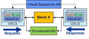
It’s not really the UVM’s fault, or the fault of the Accellera working group. Constrained-random testbench elements have inherent limitations to their reusability. Fundamentally, a simulation testbench must provide stimulus to all inputs, coordinate stimulus across interfaces, and check results on all outputs. Some testbenches may also measure coverage using any of several popular metrics. Some also check internal signals and state, possibly via assertions. Consider the following design and testbench:
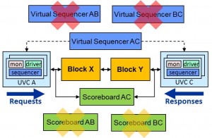
It is very rare to verify the entire design or chip only at the top level. Some level of testbench is developed for most blocks, in this case Block X. This might be an individual IP block, or perhaps a combination of blocks (“cluster”) that’s part of the overall chip. Note that this block does not contain any processors. This means that there is no need to write or generate processor code. The design can be verified entirely by a UVM-compliant transactional testbench with the verification elements shown: UVCs, virtual sequencer, and scoreboard. Many key blocks in a typical chip are verified in exactly this way. Ultimately, all of the blocks must be combined into clusters, and eventually into a complete chip design. Given the significant investment made in block-level and cluster-level verification, it would be very nice if the testbench elements could be reused as verification proceeds “vertically” by “composing” elements together at higher levels. Unfortunately, with the UVM and other constrained-random methodologies, opportunities for reuse are limited. Let’s combine block X with another block Y that was verified similarly:
Finally, a new virtual sequencer is needed to coordinate the stimulus generation on interfaces A and C. As with the scoreboard, it is not possible to compose the two block-level virtual sequencers together to form the higher-level testbench element. The lower-level virtual sequencers are useless and must be dropped when blocks are combined. In the process, all testbench “knowledge” of how interface B interacts with interfaces A and C is lost. In a deep sequential design, it may be hard (pushing on a rope) to make desired behaviors happen on interface C from interface A. There is no direct way to reuse the block-level knowledge in the cluster-level virtual sequencer. The shortcomings of the UVM for vertical reuse is one of the factors that led Accellera to form the Portable Stimulus Proposed Working Group. As we’ve discussed, we are very active in this effort and believe that graph-based scenario models are an excellent way to take the next steps beyond the UVM. In our next blog post, we’ll show specifically how graphs enable vertical reuse and how they allow block-level verification elements to be composed at the cluster and full chip levels. Tom A. The truth is out there … sometimes it’s in a blog. Tags: Accellera, Breker, coverage, EDA, functional verification, graph, portable stimulus, pwg, reuse, scenario model, scoreboard, sequencer, SoC verification, standards, UVC, uvm, working group One Response to “A Guide to Composition for Testbench Elements”Warning: Undefined variable $user_ID in /www/www10/htdocs/blogs/wp-content/themes/ibs_default/comments.php on line 83 You must be logged in to post a comment. |
|
|
|
||||||
|
|||||||
|
|||||||


You hit the nail right on the head with this one, Tom. I’m looking forward to your next post!